Note: The calculations on this page were neither calculated nor certified by a licensed engineer. All calculations for discussion purposes only. While this page is intended to be educational, students should refer to their text and professors to verify their calculations.
Built: Circa 1995
Destroyed: 10 May 2000
Length 9ft (estimated)
Type: Simple Wooden Beam
Location: Los Alamos, NM
Reason for listing: Substantial lack of planing and design, poor construction quality, and a noteworthy lack of safety measures.
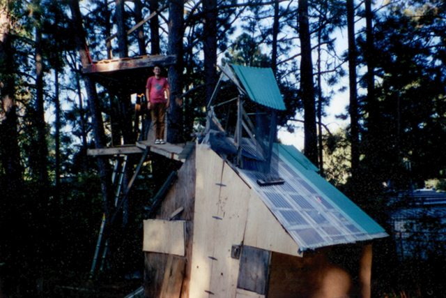
The author is not without fault when it comes to design and construction of scary bridges. Indeed, by the close of 7th grade he had designed and executed his very own scary bridge. Admittedly, in this context "designed" means "Decided that some of the 2x4s salvaged from the landfill could be spliced together and used to connect the main fort to the treefort. And wood from some old pallets would make excellent decking for said endeavor." And "executed" means "Took a saw, hammer, and nails. And used them to fasten said wood together into a bridge and install it between his two forts."
Once the bridge was installed the author was, at the time, very pleased with the result. The resulting functionality was well worth the investment. Oddly, all others refused to cross the bridge more than once. It remains unclear why anyone would, even just once, let a 7th grader talk them into crossing a bridge of his own design and construction without first insuring that it passed inspection.
Other than the lack of hand railings (and lack of a warning sign), the obvious safety question is "Even under good conditions, can this bridge hold a reasonable load?" Due to the later destruction of the bridge it is not possible to determine exact design values, nor to conduct much needed destructive testing. However, a rough estimate of the bridges strength can be made.
As with the prior bridge, page number references refer to pages in Structural Design in Wood, ISBN 0-412-10631-0.
Bridge Specifications and Assumptions:
- Basic Design: There were two support beams, each consisting of 2 2x4s spliced end to end. Each end rested on on a fort and was fastened down. Each segment of decking was cut to length, placed crosswise between the support beams, and fastened with four nails.
- A length of 9ft (108in). The exact length is not known, and is difficult to determine from the one surviving photograph. Complicating the situation, one side of the bridge was slightly longer than the other due to the angle of the two forts.
- A central support was added to reduce the frightening quantity of deflection and sway. It only attached to one of the two bridge beams, and was of a quality lower than that of the rest of the bridge. As such, it will be assumed to add a negligible quantity of support. Although it did bring the deflection within comforting limits.
- The splice in the two support beams consisted of two sections of 2x4 on either side and a number of nails to fasten it together. Without a design detail of the joint an exact strength can not be calculated. It will be assumed that the splice was as strong as the 2x4s being spliced.
- The species of wood is unknown, and grading rules do not cover "Best of what a kid dragged home from the landfill." No.2 non-dense southern pine will be assumed. Fb = 1350psi (p393)
- Beams were trade size 2in x 4in; standard dressed size of 1.5 x 3.5in. Section Modulus, Sx = 3.06in3
- The decking was continuous, consisting of rough cut lumbar about 1 x 4 in size. Actual thickness was about 1in.
- Estimated width 16in
- For this calculation, a static load will be calculated with CD, load duration factor, = 1.0 (normal duration). If a dynamic load was calculated the duration factor could be higher, increasing the calculated strength.
Estimated Bridge Strength
This gives us a maximum bridge strength of 206lbs if both beams are evenly loaded. However, a walking person could easily place all their load on one side or the other. The larger load duration factor for short duration loads (1.6 for 10min loads, 2.0 for impact) suggests that the bridge would not immediately break due to a 150lb person crossing it - but repeated use by a 150lb person could result in a failure.
Conclusion
The bridge likely would not break under occasional use of a 7th grader, provided that no extra load is carried. However, the bridge can not be considered to have adequate capacity for normal safe operation. Additionaly, due to the lack of the warning sign, this bridge fails on all counts of Don Lawson's Safety of Engineering Hierarchy.
Final Note
The eventual destruction of the bridge was indeed accidental in nature. As hard to believe as it may be, that destruction was not due to any design defect, nor was it in any way the fault of the author. Had the bridge (and fort) been properly engineered & constructed the bridge would still have been accidentaly destroyed at the same time and in the same way.
Last Update: This page was last updated on March 2014; reformatted, minor content updates.
Photo © Alice Lacelle, 1995
Other content © David C. Hunter, 2013-2014
fb {at) dragonsdawn (dot] org


